Conveyor Belt 3d Printer
Introduction
So, when I set off to tackle this project, one of my biggest pet-peeves of 3d printing was the fact that once a print was done it had to manually be taken off before a new print could be started. This meant that the max rate parts could be produced was limited by the amount of time I could spend by the printer. I could have an entire week free for printing, but if I was not there to remove the finished print and prepare the printer for the next one, that extra time was practically useless. That is why I wanted to create my own 3d printer that instead of using a plate used a roller system so that once a print was done it could "slide off” and the next part could be produced… Here is my effort at making that happen.
Inspiration
I have to admit… I did not come up with this idea myself. I was inspired to try this design out through a Youtube video I saw (linked to the right). I saw huge potential for a 3d printer like this because it would increase productivity massively. Couple that with autonomous printing and this 3d printer could have manufactured entire projects without the user having to interact with the printer. I had to try and design my own.

Here was the Z-axis schematic and my idea on how to tension the belt for the 3d printer.
Before I went about designing my own version, I created some baseline schematics just to visualize. Here are some of said schematics to help visualize my design process.

Here was the dimensioning for the Z-axis assembly. My schematic work has come a long way since high school…
The build
I have to admit… When I went about to design this build, I did not expect it to be as much work as it turned out to be, so I have not completed the build. Physically it’s all there, but code-wise there still needs to be work done and electrically it may have caught fire the first time I turned it on… more on that later.
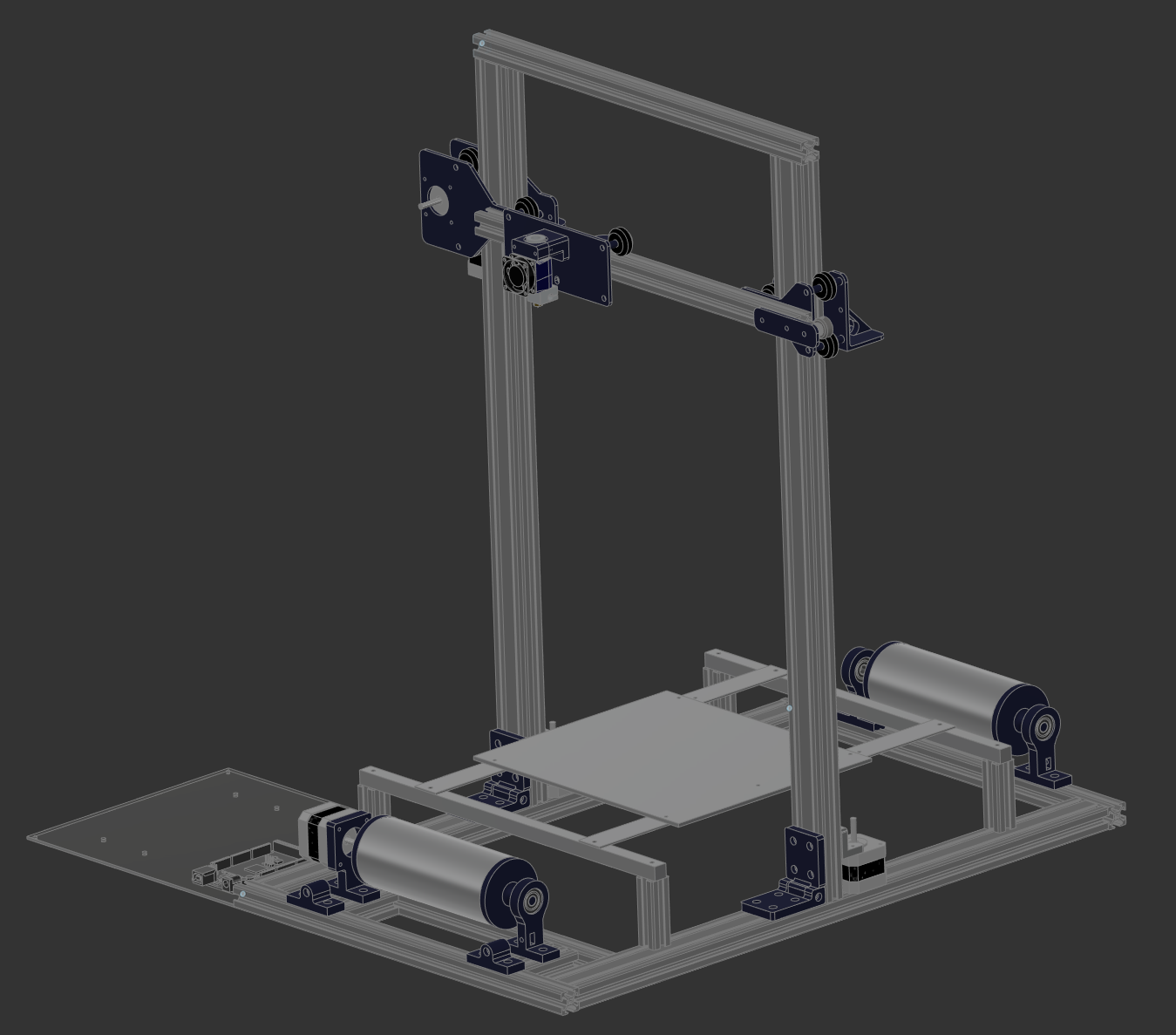
Isometric view of the completed CAD design
Tensioning the rails used a different technique. Instead of using this bolt and nut system, I made it so that one of the wheels was bolted to a rail so if the Z axis assembly or extruder assembly needed to be tightened/loosened only one wheel would need to be adjusted to get the desired result.

The hotend roller mount. The slot is underlined in red as well. This one is vertical as the 80/20 aluminum runs horizontally to this part.
So here was the design I came up with. It takes heavy inspiration from other conveyor built printers of the time such as the Workhorse MK3 and the Workhorse MK4 but everything was designed by me.
One of the biggest issues I had when designing this printer was tensioning the belt part of this printer. It was very unlikely I would be able to cut out the right size on the first try, so how did I go about solving it?

Here was the solution I came up with. The part connected to the edge of the frame would have an M4 bolt inside it while the other part had a M4 nut. If it needed to be tightened, I would turn the bolt and the assembly would move closer to the frame of the printer.

Image of the Z axis assembly. The slot mount is underlined in red.
Once I felt comfortable as to where the design was, it was time to get these parts printed out and see how it worked!

The hotend roller mount as shown earlier. The tensioning was difficult but once it was finished the part moved effortlessly!

The 3d printer around 45-50% completed.
Overall, the manufacturing of the 3d printer went well. Aside from the occasional failed part making me yearn for this printer completion that much more, each part held the prescribed load it was required to hold and had an acceptable amount of deformation!

The 3d printer nearly done. Just some cable management and a fire extinguisher and the project can be tested!
The 3d printer was coming along nicely! I was extremely proud of the tolerances around the frame and as you can see by the above picture, I needed to add more strength with additional L-beams, but once that was added, the printer was solid and I was confident in finally coding and running the printer!
The current state of affairs…
Of course, as the manufacturing went well, there was something else that was bound to go wrong with the project… And this is where the project is on halt as of this day… I flashed my board with Marlin and was prepared to test out all the motors and the hotend to see if everything worked when the magic smoke came from the board
I think I blew up a motor controller…
And after that happened, I got freaked out turning it on again as I was worried I would burn down the house. Anticlimactic — I know — but I hope as I gain more experience with electricity I can tackle this project and finally finish it.