Sheet Metal Chassis
introduction

In my team’s 2018 robotics season, one of our biggest issues was keeping under the weight limit for the robot (120lb). We struggled with it so much, in fact, that we had to "swiss-cheese” the chassis to make sure our robot was able to compete. A very band-aid solution to the problem of having a heavy chassis. It limited our ability to add new components and to add more functionality. So in the off-season, I decided to create my own chassis that was lighter and cheaper than our current solution. Here is the progress of that chassis.
OEM to IN-HOUSE

AndyMark AM14U4 Chassis
Our previous chassis design was the AM14U4 chassis from AndyMark. A tried and tested chassis that our team has used in its entire decade-long existence. We chose this chassis because of its rigidity, simplicity, ease of upgradability, and readily available parts. However, some huge drawbacks to this chassis were its cost (approx. $240) and weight (~25 lbs). For my sheet metal chassis design to be a desirable alternative, it will need to keep the simplicity and rigidity of the AndyMark frame, but also be cheaper and lighter to make the manufacturing investment worth it.
The first task was to figure out what features of the original design I would like to carry on over to the new version. Here was a list of the features I wanted to keep.
The hole arrays to easily add more modules in the future.
The bent sheet metal design to improve rigidity. Aluminum 6061 is the team’s go-to material, but has poor ductility. Therefore, aluminum 7075 was more desirable for the task at hand.
The 1/4” drop center wheel to improve mobility of device.
However, with these additions, there were things I wanted to remove/reduce as well
Sheet metal thickness to reduce weight.
Elimination of churros to reduce parts and complexity of chassis.
With this set of rules set, it was time to create my design
Mark I, Mark II, Mark III…

V1 of Chassis
Showcased on the left is my first design for the sheet metal chassis.
Notice how this design significantly reduced the amount of material through triangular cutouts. Triangles as they are the most structurally sound shape with small filets at the vertices to make this manufacturable with a CNC. However, through further observation, there were a couple flaws with this design.
These significant number of holes would increase manufacturing time and could reduce rigidity to a critical amount. The sheet metal was already reduced from 3/8ths to 1/8th thick so let that thickness reduction take care of the weight.
The side panels have a bend on the top and bottom and left and right edges. Impossible to do with the bender available in our shop.
Therefore, these changes made a redesign necessary. Further on is the redesign of the sheet metal chassis.
V2 of chassis
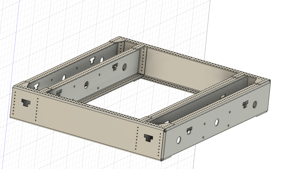
Here is the second redesign of the sheet metal chassis.
Note how this design is significantly less “swiss-cheesed” compared to the previous design. The only cutouts now are the cutouts for the bumper design that was designed alongside this chassis. The edge tabs still remained on this design, but that was due to rigidity concerns that arose throughout the development of this chassis. These rigidity concerns were laid to rest with more chassis testing later into development. As a result, there were a couple more changes that could be made to this chassis.
Remove the edge tabs featured on the side parts.
Reduce the number of rivet holes to secure the chassis together.

DXF of chassis side panel
With these changes made, it was time to produce the chassis. Our team had a CNC in-house to machine out the parts so I created DXF files to convert onto said CNC.

Bearing Flange Material (Circled in red)
One small hiccup…
One issue that arose after the manufacturing of the chassis was that the bearings we used were much thicker than the thickness of the sheet metal. Because of that, once the entire chassis was assembled, the axles did not have enough material to stabilize themselves in the compartment.
My solution to this problem was to create these surrogate plates circled in red that would be riveted to the holes that bearings would be present in. I chose this band-aid solution rather than using thicker material because I believed that this would give us the necessary thickness the bearings needed while maintaining most of the weight savings that came from the thinner sheet metal. The biggest issue would be the strength of the rivets holding the entire chassis together, but through further testing we found that the rivets could withstand normal game operation.
Conclusion

The sheet metal chassis I designed achieved the tasks it was designed for.
The AndyMark chassis was approximately 25 pounds. This sheet metal design weighed approximately 7.6 pounds — an over 75% weight reduction over the original.
Through a metal sponsor our team had, we were able to obtain the 1/8” Aluminum 7075 material for free, allowing us to produce this chassis at nearly no cost to us. The only increase was the time taken to manufacture said chassis, which was worth the savings in cost.
This chassis allowed us to add more mechanisms to our robot, allowing us to win our home competition in 2019, bringing us to FIRST State Championships in Michigan.
