3d Printed Computer Case
Introduction
One thing I have always been passionate about has been computers, and while a younger version of me LOVED huge, bulky computers for their absolute awesomeness. However, an older me has begun to value different things in life - one of those things is smaller computers. Not only can you lug them around wherever you need to go but the geometric gymnastics one has to go through to fit everything in the smallest space possible is such an interesting and exciting way to create a computer design. Because of that, I was inspired to create my own computer case design - one that would be as compact and as powerful as possible given the parts I had lying around. Here is my journey for this computer case.
Inspiration


To start off, I looked at other computer cases for inspiration. Some people opted to place their graphics card in the the PCIE slot while eithers elected to use a PCIE riser to move the graphics card to a location behind the motherboard. While more cumbersome, I deemed that the PCIE riser route was the best for me because it allows each heat-generating component their own pocket of fresh air and makes the design more aesthetically pleasing. A downside to this design would be the lack of room for cable management and the need for a large proprietary riser cable but I deemed those tradeoffs worth the looks and performance of the machine.
With that design decision out of the way it was time to make my own computer case.
The build
One skill I wanted to refine throughout this build process is my ability to master model. A co-worker showed the advantage of designing a part using master modelling and I wanted to incorporate those same principles into this design to better understand it. To get this to work, first I needed to find the right models for my design. Ideally I would have found the exact parts that I would have in my build but most models online account for only the most popular SKUs. As a result, I went with models that featured either the same size or power connections so that I would be able to model around those key points.
From left to right: SFX Power Supply, Mini ITX Motherboard, RTX 3080 GPU, Noctua L9a Cooler.
With these components laid out it was time to model the computer. Following is the design.
Since this was a 3d printed case, heat-set inserts play a huge part in ensuring the components would fasten to the assembly. I opted to use M3 x 0.5 inserts as M3s are the screws most commonly found on computer builds. Since they were rated for other computer cases I wanted to take the guesswork out of what fasteners to use and just incorporated them myself.
The motherboard and graphics card are secured onto the case using heat-set inserts while the power supply uses its own 6-32 fasteners. Looking back it would have been nice to make sure every piece of hardware could be removed with the same tool but that will come in another update.
With Master Modelling it was extremely easy to ensure that the case would fit the computer components. The hardest part about the design was ensuring that the computer had the right PCI fastener location but luckily this post online helped to explain the geometry needed to make it work.
Overall this design looked great off the bat so it was straight to the 3d printer to get it working.
Printing Woes
The computer case with the pegs printed in.
In its current form this computer case was too large to be placed in my 3d printer so I decided to split it up and find a means to secure it back together. My first thought was to incorporate the pegs and holes needed in the print because I wanted to use less hardware… That was a painful lesson to learn.
It was foolish to try and replace the job of a dowel pin on this design since the risk of one of these pegs snapping off/not fitting/not printing properly would have resulted in the entire print being a failure. For the next designs, I removed the pegs and converted the geometry to accept a dowel pin instead. More hardware was required to make this happen but it ensured everything would fit together and was worth the tradeoff in parts.
The case with dowel pins attached ready for assembly.
Final REsults
Proposed case cover design. Possible but some geometric changes will be needed to the computer case.
After this dowel change and a couple of small geometric changes I reached a point where I was satisfied with this design and printed out a final version. Originally I designed a cover that would showcase the advantages of 3d printing however due to the bulk of the cables it was unrealistic to try and place the enclosure over it. Overall, I like the open-air design a lot and if I wanted to include the cover I could just print another case that would accommodate it.
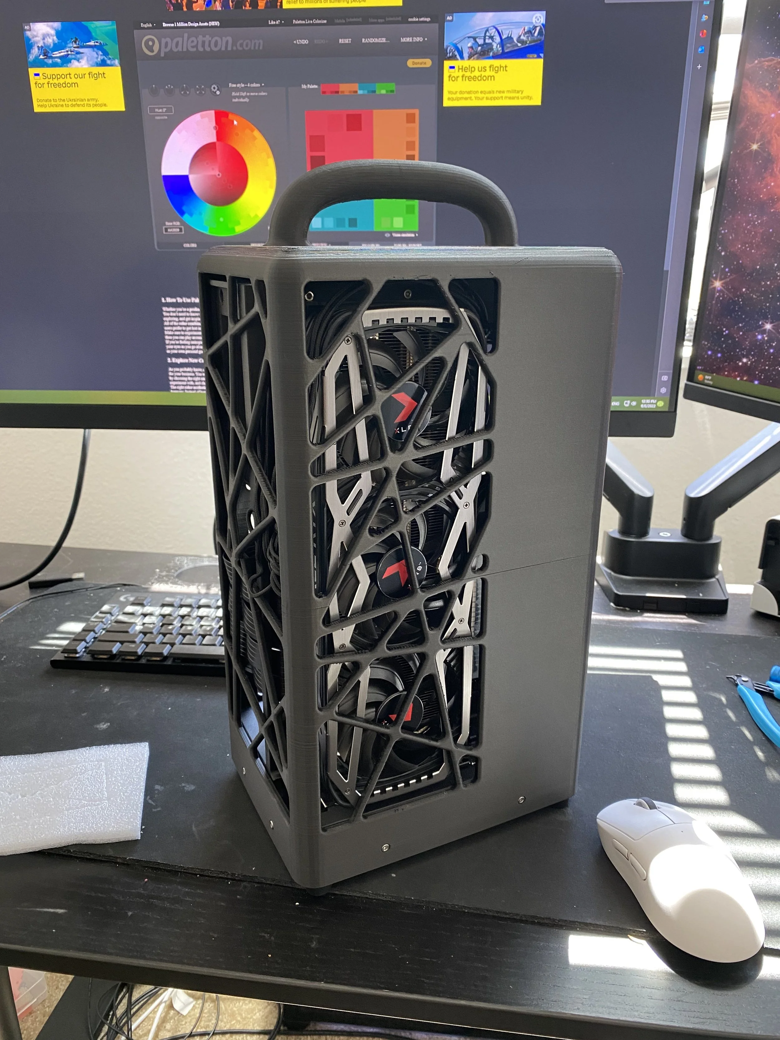
UPDATE: I decided to throw caution to the wind and printed the enclosure shown to the left. The cables do bow out the cover a little bit but this action can be remedied through better cable management. Overall, the look of the open-air and the closed off case provides a unique take on the small form factor design.
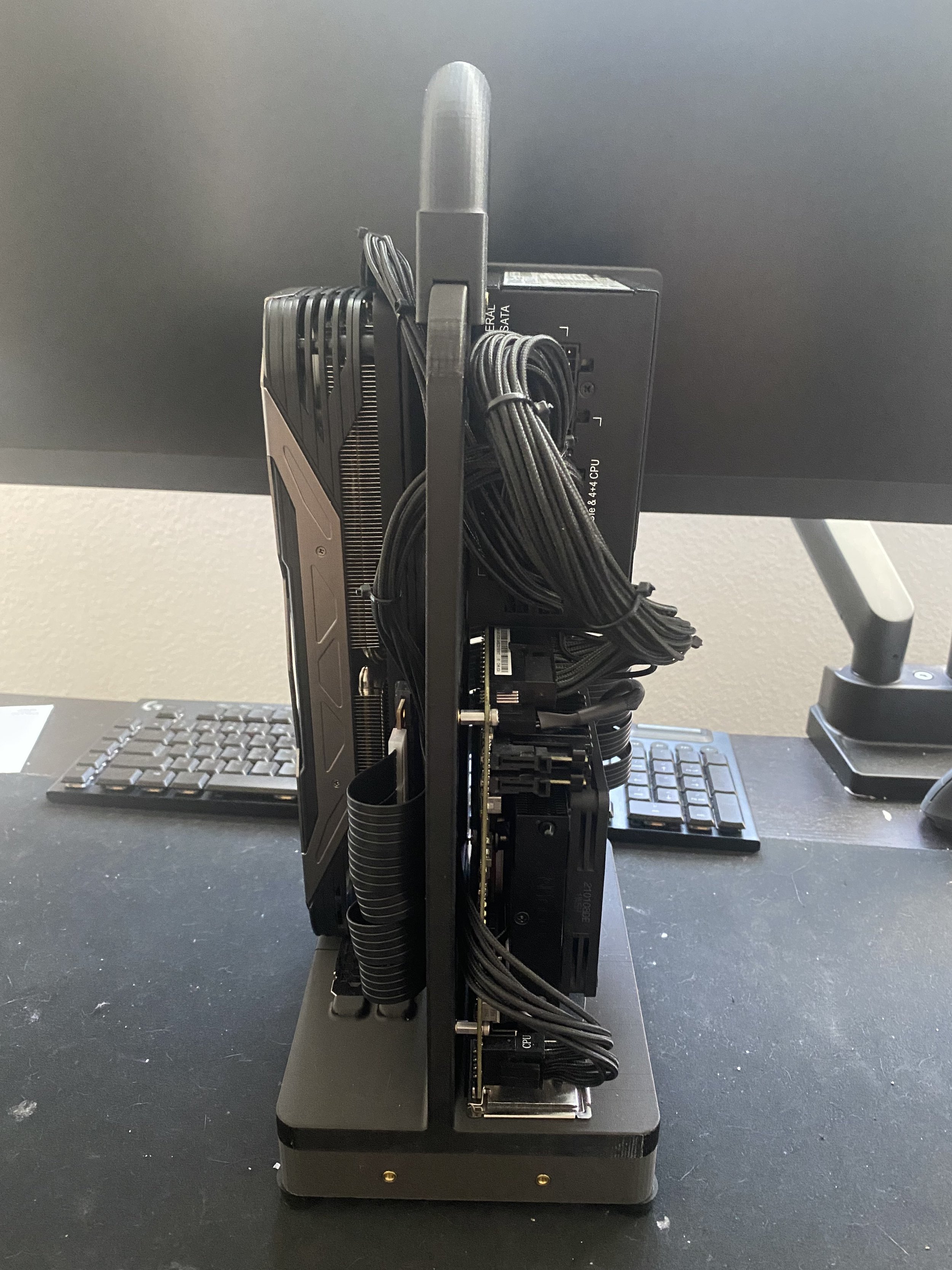
The build was a great way to refine my master modelling skills and I’m glad I took on this project! Following are more pictures of the final build.


